Emulating the Etch-A-Sketch Animator -- Part 1

Recently I was rummaging through my electronics junk box and pulled out my old childhood Etch-A-Sketch Animator, an electronic toy released by Ohio Art in 1986 as a follow-up to its classic two-knobbed drawing device. This version could save up to 12 pixelated images and animate them, using the power of an LCD screen and embedded microcontroller.
I had a ton of fun with this thing back in the day, making weird animations of cities being blown up by aliens and so on. Nostalgia prevented me from simply e-wasting or eBaying it away, so I decided I needed to come up with some sort of project for it.
I recently learned that the MAME emulator – famous for meticulous re-creations of classic arcade games – had started adding emulation models (or “drivers”) for hand-held electronics, including toys such as Simon and the Speak & Spell. But notably missing from the current list of MAME drivers was the Etch-a-Sketch Animator! Well, this sounded like a project – what if I reverse-engineered the device, and created an emulation model for it, making my own contribution to MAME’s extensive archive of emulated nostalgia?
The fact that I’ve never programmed a MAME driver before and don’t even know where to start just means this project will also be a huge learning opportunity. But before I even get there, I need to crack this thing open and see what’s inside. Here’s a tear-down video done by Joe’s Computer Museum:
My Animator’s board has basically the same components, but is clearly a different revision. Whether it’s older or newer is hard to tell, but it has a copyright mark of “1985”:
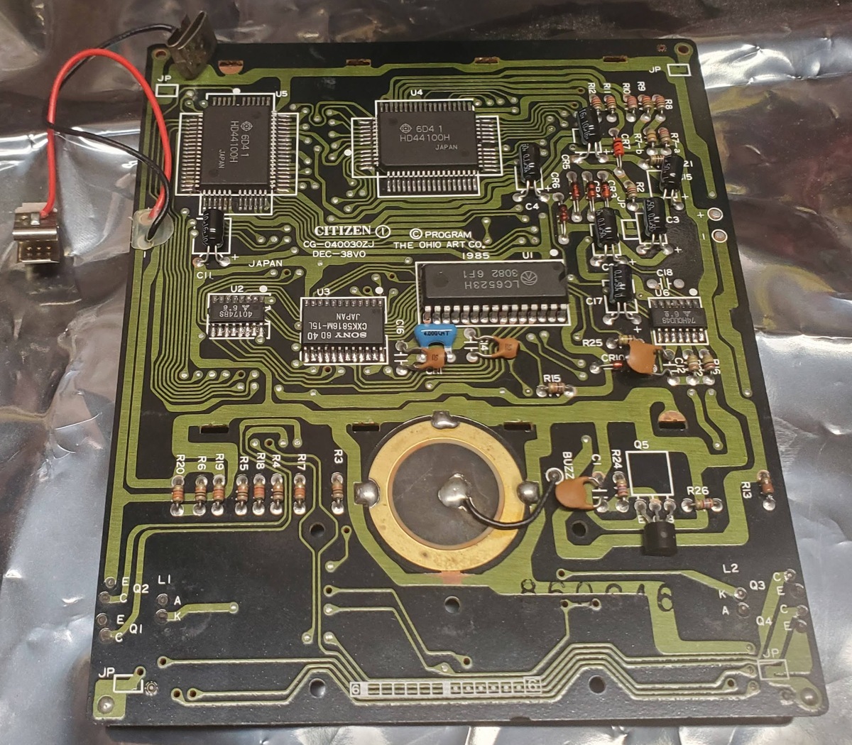 The Etch-A-Sketch Animator’s Logic Board (1985)
The main functional components on the board are:
- Two HD44100H LCD Drivers
- 2k SRAM (CXK5816M-15L on mine, TC5517AFL in the video)
- The star of the show, the LC6523H Sanyo 4-bit microcontroller
The datasheet for the HD44100H is readily available, and in fact several existing MAME drivers mention it already, including the TI Compact Computer 40 and the Mephisto Milano Chess Computer. However, in those cases the driver actually models the HD44780 LCD controller which drives the HD44100H’s, whereas in the Animator they appear to be bit-blasted directly from the microcontroller. This means some additional modeling work will be needed to emulate the display logic.
The LC6523H microcontroller, on the other hand, is a bit of a mystery. I couldn’t find a datasheet for this part, but from this list of replacement parts I could identify a supposedly compatible updated equivalent, the LC651432F (datasheet here). Both microcontrollers appear to be part of the Sanyo “65xx” line with a common instruction set and internal architecture, which I found documented in the datasheet for yet another part, the LZC6546F (instructions start on page 47).
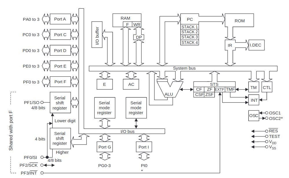 Sanyo 65xx Microcontroller Architecture Diagram
Other than not having the full documentation available, there are two more challenges with the LC6523H uC. One is that there is no MAME model for it, or any of the 65xx devices, so I’ll have to write one from scratch. The other is that the program ROM for the microcontroller cannot be read out. It is mask programmed, which means to extract the ROM will require decapping the chip’s package and decoding its mask layers bit by bit under a microscope. I don’t have the equipment or experience to do that, but there are some resources near me I hope to get some help from. And ultimately, I won’t really know if I have the instruction set modeled correctly until I can test it on the real code!
But I’m getting a bit ahead of myself. Before I do anything destructive, I wanted to start by reversing the PCB to see if I’m at least on the right track in terms of the device pinouts. My initial sketch from checking basic connectivity is a bit of a mess, but it captures the basic structure:
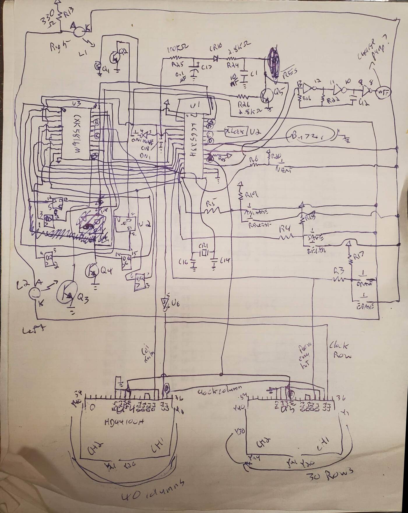 Roughly drawn schematic from reversing the Animator’s PCB
I’ll be cleaning this up into KiCad later, but for now this was good enough to confirm that the LC651432 is in fact pin-compatible with the LC6523, and to get a general sense of how the microcontroller’s I/O ports are hooked up to the surrounding circuitry. I’ll leave those details to the next post, but for now I want to point to one more interesting resource I came across: what appears to be the original patent for the Animator, US4764763A “Electronic sketching device.” This patent contains the following diagram, which lines up pretty well with the actual circuitry:
 Etch-A-Sketch Animator block diagram from the patent filing
So what’s next? There are a lot of steps to get from here to a fully-working MAME driver, and I hope to write several posts covering the entire process. This will include (but is not necessarily limited to):
- Determining the function of every I/O pin on the microcontroller
- Doing some logic analyzer captures to observe the real-time behavior of the circuit
- Setting up a basic MAME driver with basic device models for all the components
- Emulating the main microcontroller, based on the instruction set documentation available
- Testing out the above driver with some “dummy” code to see the hardware functioning inside MAME
- Finally, decapping the uC and attempting to read out its ROM to test the hardware model on the “real” code.
I don’t have the most … reliable track record when it comes to finishing projects, so who knows how long all this will take. But I’ll give it my best shot! So stay tuned for the next installment, coming … soonish?